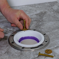
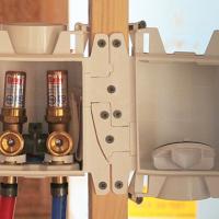
We offer 3 different fitting adaptors for our pans:  #34086 - 1” inside & 1½” over PVC Adaptor. This adaptor allows you to solvent weld a piece of 1” PVC or a piece of 1½”PVC pipe into the adaptor. #34088 – 1” inside & 1½” inside PVC Adaptor. This adaptor allows you to solvent weld a piece of 1” PVC pipe into the adaptor, or solvent weld a 1½” PVC fitting hub onto the adaptor. #34089 - 1” CPVC adaptor. This adaptor allows you to solvent weld a piece of 1”CPVC into the adaptor hub. If you need further clarification on these installation options, please contact customer service and they can send you an illustrated copy of application instructions.
You should always check with your local building and fire officials before installing a plastic pan above a finished ceiling. If the return air to the furnace is not isolated through air tight duct work or the open ceiling is used for the return air, the plastic pan should never be used. If the plastic pan is used in these applications and exposed to flames, the toxic smoke can be drawn back to the furnace and distributed throughout the building.
The plastic pan is not approved for gas water heater installations, and the aluminum pan must be used. The plastic and aluminum pans are approved for electric water heater installations.
3.5 PSI with less than a 1 PSI pressure loss over the time period called out in the tables.  
5 seconds
Concrete pipe is porous and the ASTM guidelines give allowances for this porosity. 
Owner’s Manuals and parts lists on all Cherne equipment can be located in the technical section of the Cherne website. http://www.cherneind.com/Data/ “pieces parts” – replacement parts for the hydrostatic test pumps and joint testers. We do not stock engine parts.  
3.5”
This calculation is important to the end user and helps them understand the forces behind the plug so that they can decide the proper way block the plug.
Backpressure is measured either in terms of feet of head or psi.   Feet of Head. Simply stated “feet of head” is the height of water above the centerline of a plug. For vertical pipe the calculation is easy. Simply measure the height of the pipe and that is the footage of head pressure. For horizontal pipe, feet of head is still simply the height of water above the plug. There are various ways to determine this height base on knowledge of the actual application. For example, if you have a 300’ long section of pipe at a 1 degree slope, the feet of head is 3’. (300*.01) PSI - This measurement is typically done with a pressure gauge. #’s (pounds) of Force. This is the calculation to determine how much force is being held back by a plug. It is useful information when trying to design a plug blocking system for a specific job. Calculating pounds of force for air pressure tests.   PSI *square inches of pipe opening = #’s of force Example:  8” and 5 psi test.  Pipe area = Pi R2 * (3.14*42=.50.24”).  50.24” * 5 PSI = 251.2 #’s of force. Calculating pounds of force for head pressure applications. Convert Feet of Head to PSI and then do calculation above. PSI = Feet of Head *.434. Example:  8” pipe at 30’ of head.   Pipe area = Pi R2 * (3.14*42=.50.24”) 30 Feet of Head *.434 = 13.02 13.02 * 50.24 = 654 lbs. of force. One foot of head to psi conversion chart is attached for your reference.  Feet of head psi ratings for each Cherne plug can be found in the Cherne catalog.